
Video version:
This is a guide into how to implement a Post Process based Scopes. If you have experience with Unreal you know that usually how scopes are implemented is by Picture-in-Picture. There are many guides that you can find for that method in the internet.
Links to some Picture-in-Picture Scope guides:
- https://www.youtube.com/watch?v=omcEMAy6by0
- https://www.youtube.com/watch?v=MKEpnjUFRFs
- https://www.youtube.com/watch?v=incdX4f0DL4
- https://www.youtube.com/watch?v=wxr7a7Rphws
The main problem with Picture-in-Picture scopes are they are usually very performance hungry.
In this guide, I’m introducing method that aims to be light on performance while still achieving the desired effect of a Picture-in-Picture.
Disclaimer
- Make sure you’re familiar with Picture in Picture Scopes. This guide assumes you are familiar / have used Picture in Picture Scopes in the past.
- This is not industry standard and an experimental implementation. It might be hard to find solutions for edge case problems.
- Not a flawless solution, much like a Picture-in-Picture method. There are caveats and issues
Step 1: Make the post process material
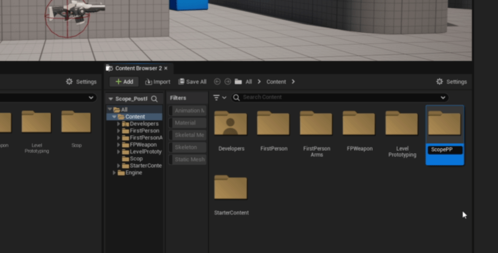
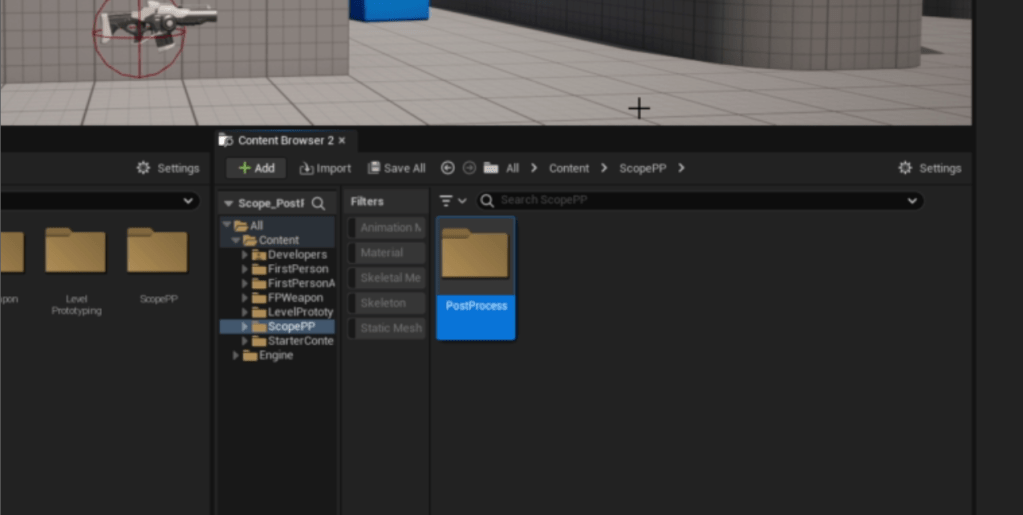
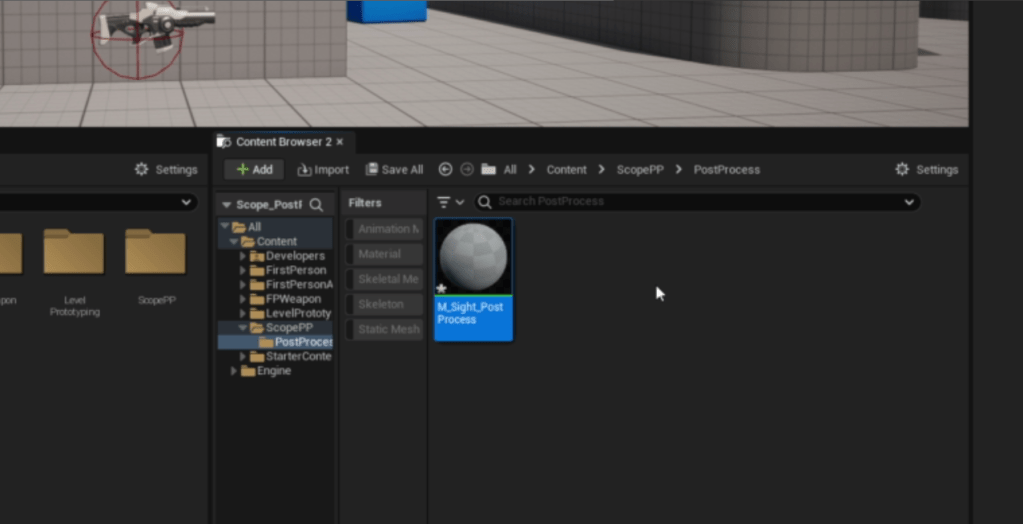
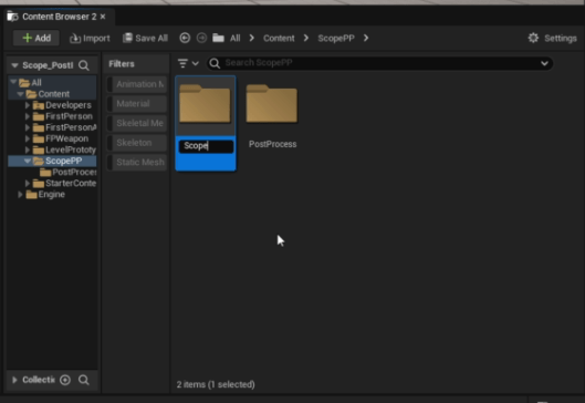
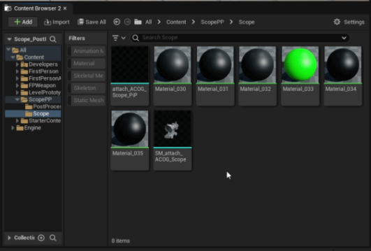
In the Content folder, create a new folder named ScopePP and under that create another folder named PostProcess just to keep things tidy.
Open that, create a Material and name it M_Sight_PostProcess.
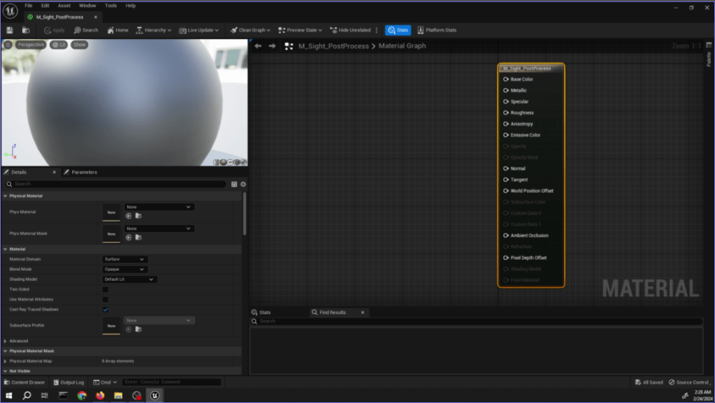
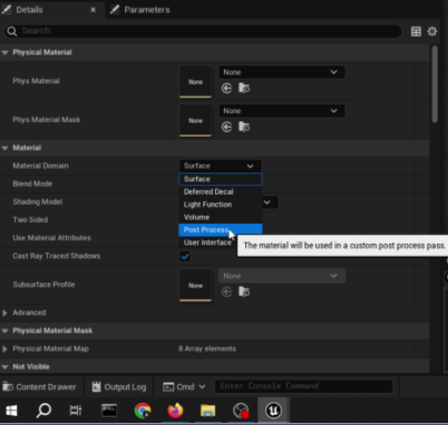
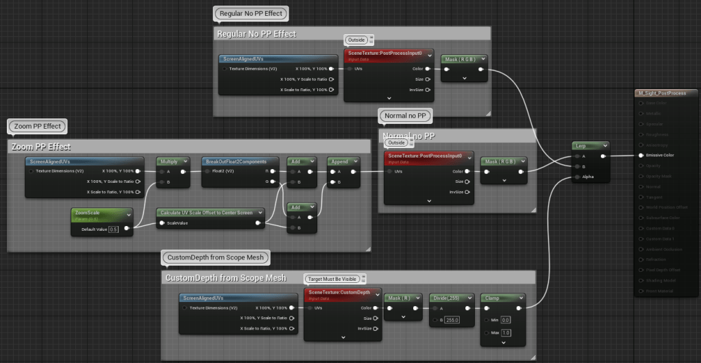
In the material node:
- Select the end point of the material, change Material Domain to Post Process.
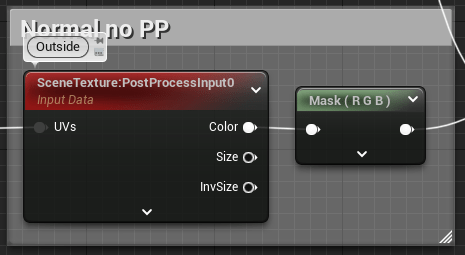
Creating the Post Process of the peripheral view (outside of the scope):
- Create a ScreenAlignedUVs node.
- Create a SceneTexture node, change the Scene Texture Id to PostProcessInput0. Connect the X100%, Y100% out pinfrom ScreenAlignedUVs node to UVs in pinfrom SceneTexture node.
- Create a ComponentMask node, connect Color out to the mask node. In it make sure R, G, and B are checked.

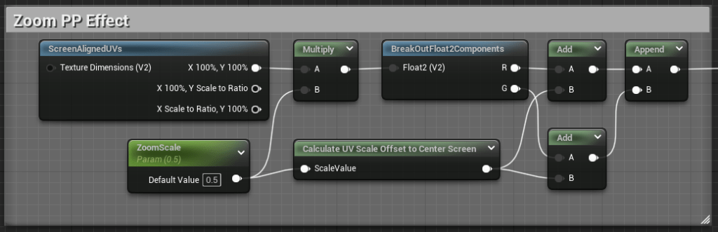
Creating the Post Process of the zoomed scope area (inside of the scope):
- Create a ScreenAlignedUVs node.
- Drag X100%, Y100% pin, then create a Multiply node.
- Create a ScalarParameter node, name it “ZoomScale”, make the Default Value 0.5 for testing purposes. Connect the out pin to the B pin in the Multiply node.
- Drag the out pin from the Multiply node and create a BreakOutFloat2Component node.
- Drag out both the R and G out pins, create an Add node for both of them.
- At the end create an AppendVector node, and connect the Add nodes to it.
- Create a Custom node, to explain it short this allows you to create a small snippet code.
- In the Custom node, change the output type to CMOT Float 1.
- Change the description to which you like. I named mine: Calculate UV Scale Offset to Center Screen.
- Next, under Inputs, Index[0], change the Input Name to ScaleValue.
- Now on the code part. Change the code field to:
- ((1 – x) * 0.5) % 0.5
In code:
return ((1 – ScaleValue) * 0.5) % 0.5;
- ((1 – x) * 0.5) % 0.5
- Connect the ZoomScale node to the Custom node in the ScaleValue pin.
- Connect the Custom node to both of the Add nodes.

Now create the same Scene Texture and Append node from earlier.
- Copy the SceneTexture node and Mask node we made earlier. Paste them beside the Zoom Post Process section.
- Connect the out pin from the Append node to the UVs in pin in the SceneTexture node.
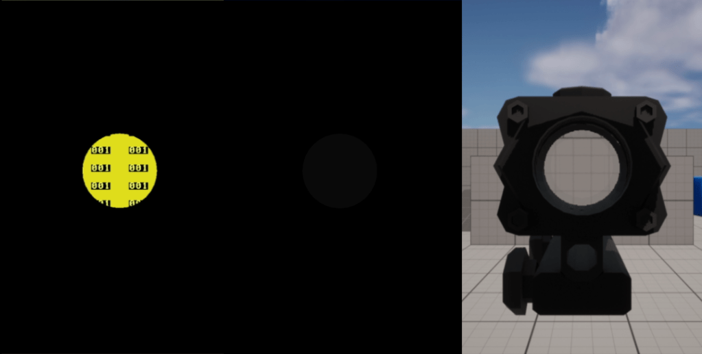
Creating the Scope Post Process Mask layer (where the magnification is on screen):
- Create a ScreenAlignedUVs node.
- Create a SceneTexture node, change the Scene Texture Id to CustomDepth.
- Copy an earlier ComponentMask node, this time make sure only R is checked. Connect the Color out pin to the ComponentMask pin.
- Drag out the ComponentMask out pin and create a Divide node. Change B value to 255.
- Drag out the Divide out pin and create a Clamp node. No need to change the values.

Now create a LinearInterpolate node.
- Connect the Non-Zoomed section output pin to the B pin of the Lerp node.
- Connect the Zoomed section output pin to the A pin of the Lerp node.
- Connect the Lerp out pin to the Emissive Color pin of the Material node.
- Connect the PostProcess Mask section output pin to the Alpha pin of the Lerp node.

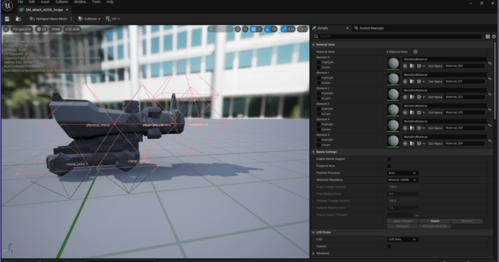
Step 2: Import Demo Meshes
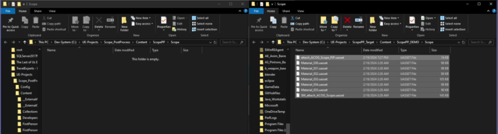
- Download the uassets in this zip file.
- Create a new folder named “Scope”.
- Right Click select “Show in Explorer”
- In the Folder, place the uassets you downloaded.
Step 3: Setup FPS Blueprint
Add meshes to BP:
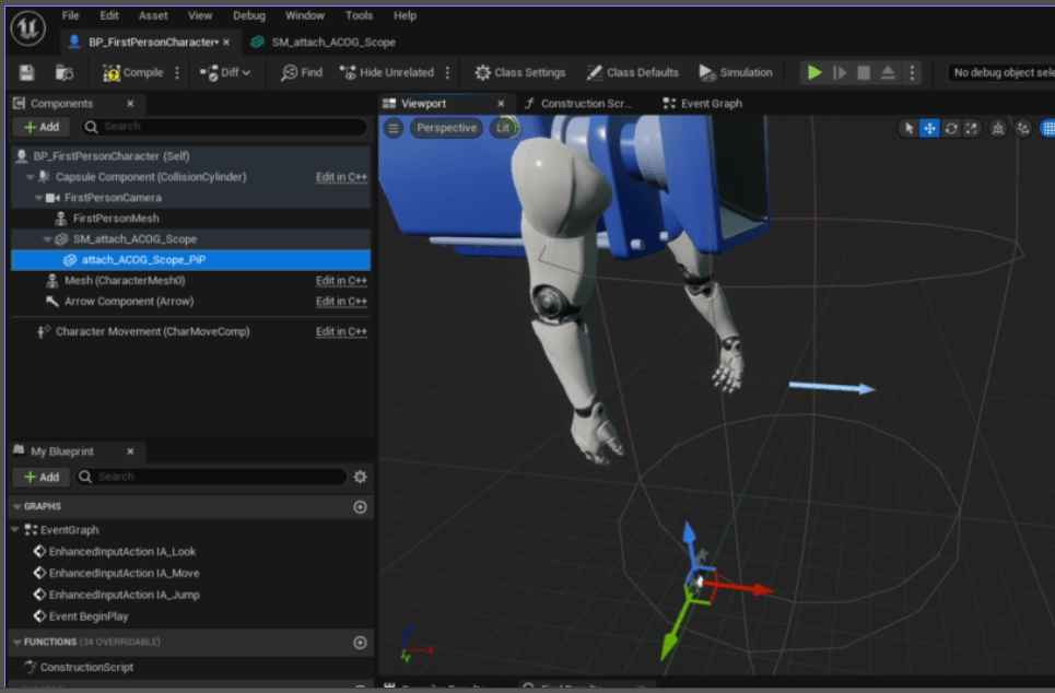
- Find the FPS Character Blueprint under First Person > Blueprints named BP_FirstPersonCharacter. And open it.
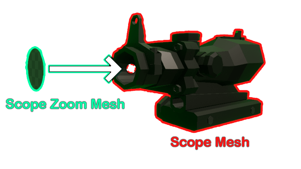
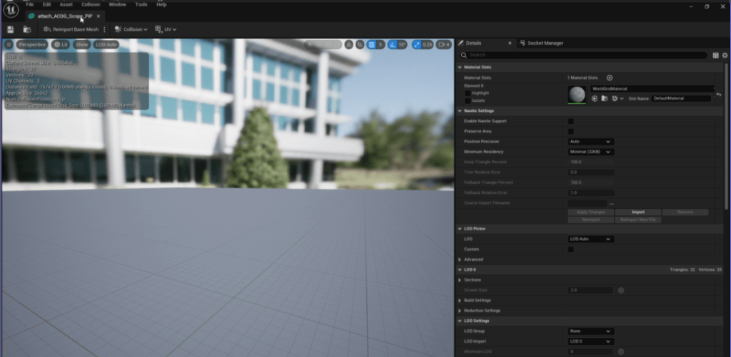
- Next Place the 2 demo mesh at the camera, here I just dragged the meshes into the blueprint.
- Arrange the meshes this way. The Scope Mesh is attached to the Camera. The PostProcesss Mask Mesh is attached to the Scope Mesh.
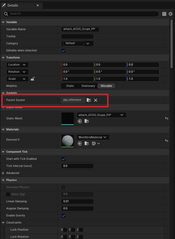
- In the PostProcess Mask Mesh, change Parent Socket to pip_reference. Make sure all transforms are at default.
- Adjust the Scope Mesh so it’s in the view of the Camera. If you’re following, make the Location: x:18, y:0, z:4.7; make Rotation: x:0, y:0, z:-90

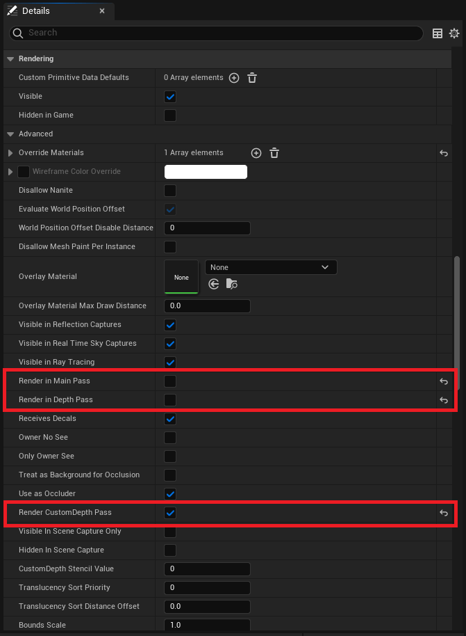
Set SceneDepth settings:
- In the PostProcess Mask Mesh details:
- Under Rendering > Advanced > uncheck Render in Main Pass and Render in Depth Pass.
- Check Render CustomDepth Pass.
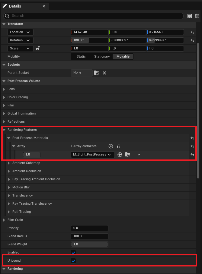
Add post process to BP:
- Add PostProcess component to your blueprint. Attach it anywhere, I attached it to the camera.
- Make sure Unbound is checked.
- Under Post Process Volume > Rendering Features > Post Process Materials:
- Add an array element and select the Material we first created “M_Sight_PostProcess”.
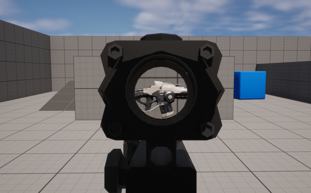
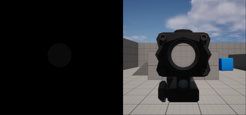
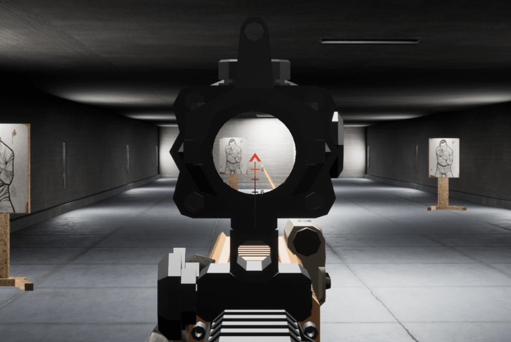
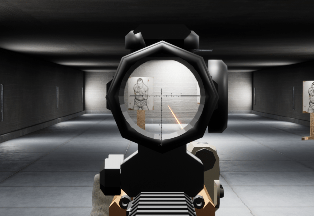
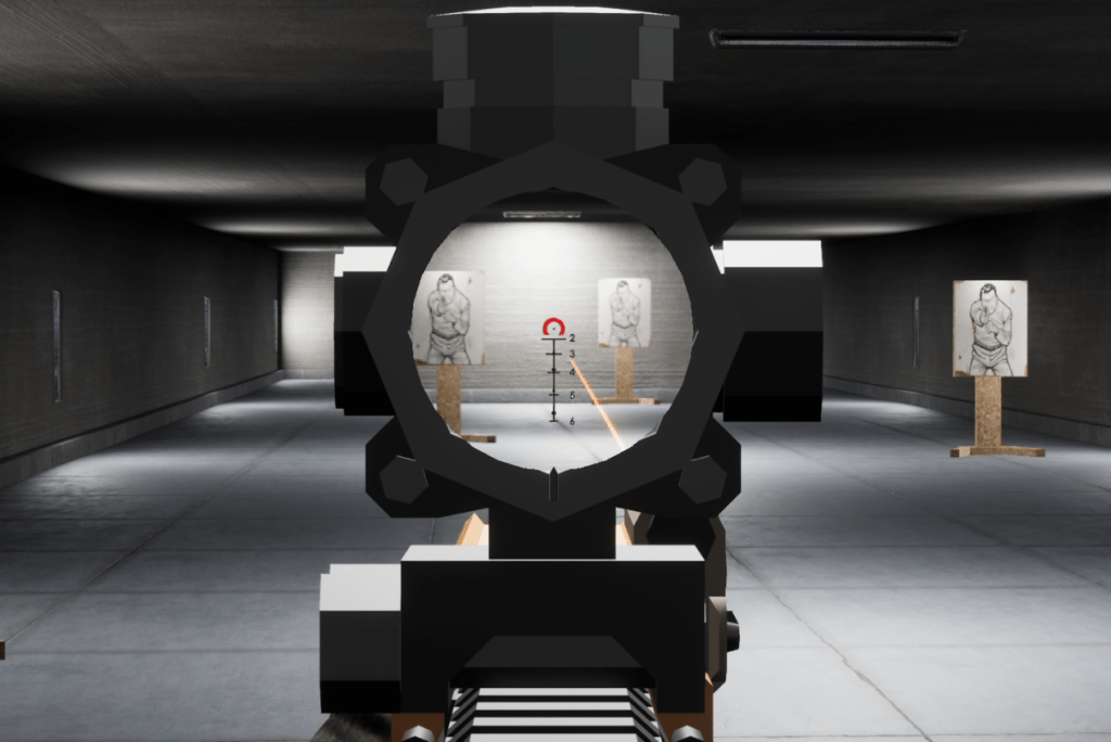
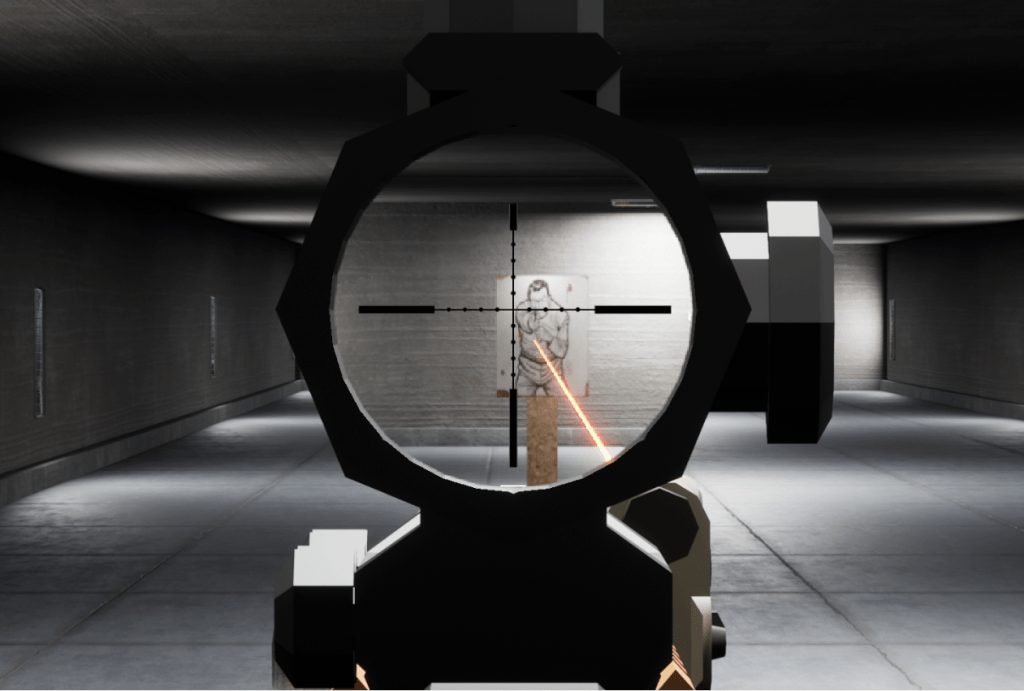
Final Result

To compare

Things to Keep in Mind
- This implementation uses Custom Depth.
- This implementation uses Custom Depth. This might cause some conflicts to other features that might use this same feature. There are other plugins or marketplace add-on that uses this. In the event you want to use this implementation my next point will be important…
- Learning about Stencil Depth and modify your implementation.
- Learning about Stencil Depth is mandatory if you plan on implementing multiple features that take advantage of the Custom Depth feature of unreal. This is also required if you’re planning on adding special kinds of features on Scopes like Thermal as I guarantee you’ll also need Custom Depth to mask the Players with thermal.
- Links to some Stencil Depth guides:
- Image Quality concerns.
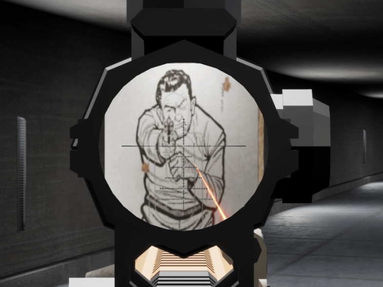
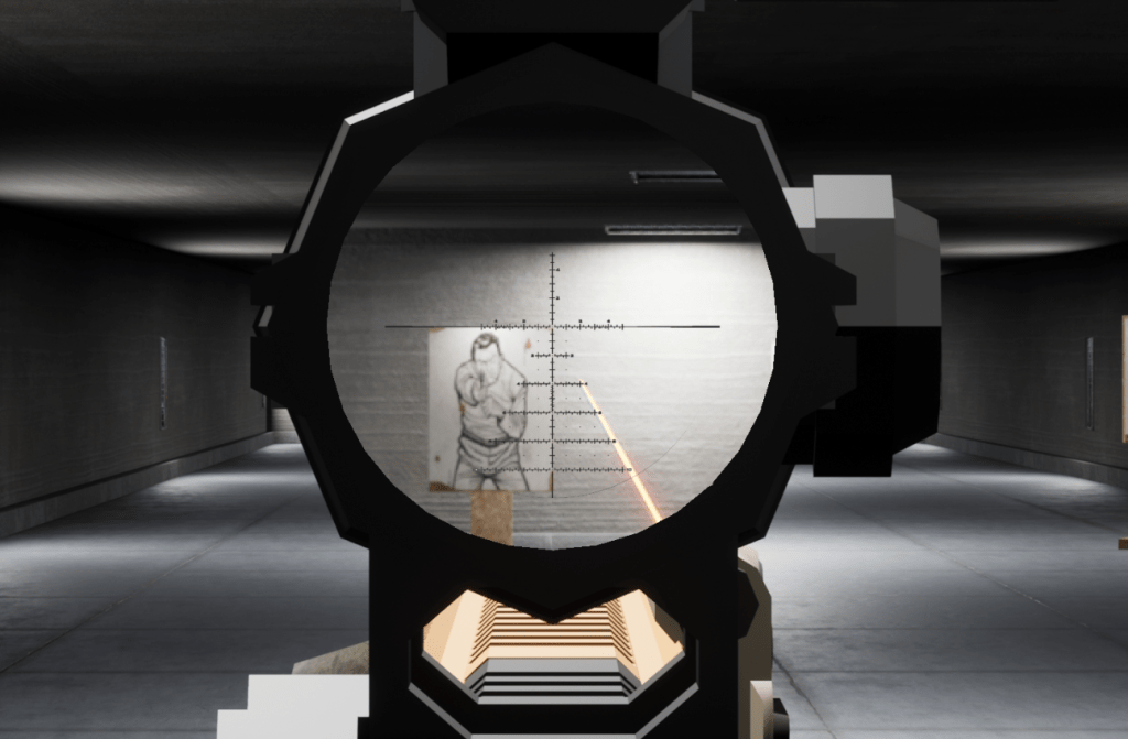
- The performance advantage in this approach is great. Unfortunately, the greatest weakness of this approach is the Image Quality.
- To elaborate how the magnification works, the zoom effect is stretching the Pixels on the screen. This means that if you push the magnification too much. The image on the scope will be unreadable.
- It’s up to you to decide how you work around this, resolution scaling maybe? Personally, I like to play around the camera FoV in tandem with the PostProcess zoom to get a desired result.
- Beyond Post Process Scopes.

- You can use this method of magnification not only on scopes. You want a little bit of magnification in a small red dot? Definitely possible with barely any performance impact. You can even design NVGs / Visors this way.
Miscellaneous References:

[…] Haven’t seen part 1? Check it out […]
LikeLike